High-Temperature Tensile Testing Machine
◆ Brief Description
Used for high-temperature strength testing in accordance with GB/T4338 "Metal Material High-Temperature Tensile Test Method", HB5195 "Metal High-Temperature Tensile Test Method", GB/T2039 "Metal Creep and Rupture Test Method under Tension", and HB5150 "Metal High-Temperature Tensile and持久试验Method".
◆ System Composition
The electric furnace system consists of: high-temperature furnace body, temperature measurement and control system, heating elements, temperature sensing elements, adjustable support arm system, high-temperature tensile clamps and connecting attachments, high-temperature deformation measurement devices, and water cooling circulation system.
◆ Product Overview:
The microcomputer-controlled electro-hydraulic servo universal testing machine operates by sending control signals from a computer to a servo valve, which controls the opening and direction of the valve, thereby controlling the flow rate of oil entering the cylinder. This achieves closed-loop control of constant test force, constant displacement, and other parameters. It is capable of conducting tensile, compressive, and bending tests on metal materials, non-metal materials, product parts, components, structural components, and standard parts. With the addition of an environmental device, this series of testing machines can also perform tensile, compressive, and bending tests on materials in specific environments, such as high-temperature tensile, low-temperature tensile, compressive, and other tests.
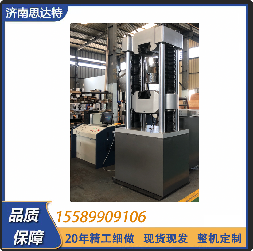
1. Main Unit
The main unit features a four-column double lead screw structure with a lower-mounted cylinder, placing the tensile test space above the main unit and the compressive and bending test spaces between the lower beam and the worktable.
2. Transmission System
The lifting of the middle beam is achieved by a motor driving the rotation of the lead screw through a sprocket, adjusting the spatial position of the middle beam and realizing the adjustment of the tensile and compressive spaces.
3. Hydraulic System
Hydraulic oil in the oil tank is pumped into the oil circuit by a motor-driven oil pump, passing through a check valve, high-pressure filter, pressure differential valve group, servo valve, and entering the cylinder. The computer sends control signals to the servo valve, controlling the opening and direction of the valve, thereby controlling the flow rate of oil entering the cylinder and achieving control of constant test force and constant displacement.
Serial Number | Item Name | Parameters
--- | --- | ---
1 | Maximum Test Force kN | 300 kN
2 | Relative Error of Test Force Display | ≤±0.5% of the display (upgradable to 0.005%)
3 | Test Force Measurement Range (Sensor Accuracy) | 0.02% to 100% of the maximum test force
4 | Constant Stress Control Range (N/mm²·S-1) | 2 to 60
5 | Constant Strain Control Range | 0.00025/s to 0.0025/s
6 | Constant Displacement Control Range (mm/min) | 0.5 to 50
7 | Clamping Method | Hydraulic Clamping
8 | Diameter Range of Round Specimen Clamping mm | Φ6 to Φ40
9 | Thickness Range of Flat Specimen Clamping mm | 0-30
10 | Width of Flat Specimen Clamping mm | 80
11 | Maximum Tensile Test Space mm | 640
12 | Maximum Compressive Test Space mm | 600
13 | Control Cabinet Outer Dimensions mm | 1200×620×850
14 | Main Unit Outer Dimensions mm | 770×650×2040
15 | Motor Power kW | 2.1
16 | Main Unit Weight kg | 2100
17 | Net Distance Between Columns mm | 480
18 | Upper and Lower Press Plate Size mm | Φ150
19 | Bending Support Stick Spacing mm | 400
20 | Bending Support Stick Width mm | 140
21 | Allowable Bending Degree mm | 100
22 | Maximum Piston Stroke mm | 200
23 | Maximum Piston Moving Speed mm/min | Approximately 80
24 | Test Space Adjustment Speed mm/min | Approximately 150